II - main disk and clamp
|
The next thing to make is the main disk (I). This is a 12" diameter
plywood
disk. I made it by hand-cutting it a little big with a small coping saw.
I have a contraption to hold my router upside down; this turns it into a
small routing table. Believe me, this is worth the work. I finish the
disk on this routing table, by rotating the disk on a nail through the
center, past a straight router bit to make a perfect circle.
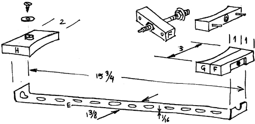
The drawing below is of the piece that clamps onto this disk. The metal strip runs underneath the disk, and is therefore mostly not visible in the photos. |
|
|
The metal piece (E) is like the stuff plumbers use to hang pipes, except a
little thicker and wider. Cut and hammer it into shape, and make sure you
have a hole in the middle where the center of the disk will be.
Pieces (F) and (G) are drawn twice. The nails that stick out of (G) slide in holes in (F). In (F) I cut a hexagonal hole for a nut, in which a piece of threaded rod goes. On the end of the rod I filed a narrow section, which fits into a small washer which is embedded in (G). |
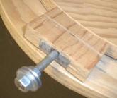 When you turn the rod,
it pushes against the washer in (G), forcing (F) and (G) apart. This is
how the clamp works.
The bottom piece of plywood in this photo is the slanted part of the base (C). On the top right you can see a part of the disk. |
|
By turning the screw in the previous picture, you can clamp blocks
(G) and (H) shown in this figure, to the disk.
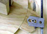
I would initially cut piece (H) a bit long. Then I would finish the disk (I), the metal piece (E), and pieces (G) and (F). After you fit all those together you can determine just how long (H) has to be. In the middle of this block (H) is a 3/8" dowel that sticks up a little bit, and this dowel rides in a groove filed in the flat piece of metal (Q) visible in the photo. A big washer and a small screw keep the metal onto the dowel. Piece (Q) is cut from the same metal as (E). A pair of holes is filed out so the dowel can slide through it, with no play. Two nuts are soldered to the bottom. I thread them onto the rod, and clamp this to (Q). Then I soldered it with a torch and ordinary flux-core solder. (No torch? The flame of a gas stove works too).
|
 |

|
|
If you turn the rod counterclockwise, the nuts will ride up, taking the
flat metal piece (Q) with them. This piece pushes on the dowel that rides in
the slot, and if the block (H) is clamped to the disk, the disk will slowly
turn counterclockwise.
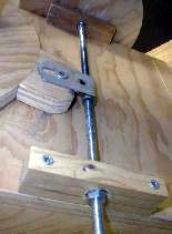
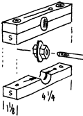
Here you can see that the rod rides in two bearings (S) on either side of
the slanted plywood surface (C), one on the foreground, and an identical
one in the background. Part of the handwheel can be seen in the background
too.
On the rod in this spot are two nuts holding a big washer (there is a third nut, added to the outside, so it sticks out of the bearing, as you can see in the photo). The washer rides in a slot cut into the wood, allowing the rod to turn, but not to move up, down or sideways. Of course you can't cut a slot like that unless the bearing block comes apart along the middle, which it does. You can see the two screws that hold the two pieces together, and hold both pieces to the base. |
|
|
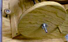 Turning around to the other side of the rod, you can see the handwheel,
which is held with a washer and a wing nut. This allows you to easily
switch the wheel from one side of the sunspotter to the other side. If you
use the sunspotter at sunrise, you'll have to switch the wheel, or it will
be in the way of the cardholder. The wheel is 8" diameter, cut the same way
as the big disk. A small dowel makes a little crank.
|